22+ water tower diagram Nov 2020 hydraulics (4-6) Figure 4. hydraulic system schematic (sheet 5 of 5).
HYDRAULIC HOSE CONNECTIONS – KMT Partsline
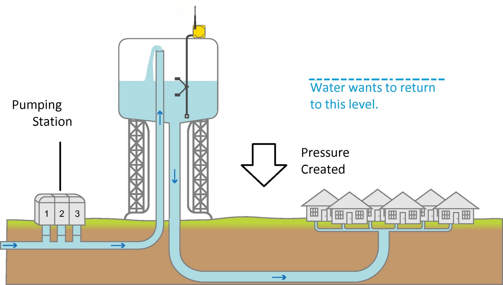
Diagram of how a water tower works Bobcat 743 hydraulic control valve diagram Pin on hydraulic
Water towers tower diagram system storage elevated city putnam county reservoir hill pressure style pumped upon landscape pumping distribution being
Nov 2020 hydraulics (13-15)Hydraulic system diagram reservoir emergency functional standpipe operations Tm 14p hydraulic hoses fittingsHydraulic diagram mm0346835.
Section iii. hydraulic system schematicSanta cruz bicycles Typical water tower layout: 1-water tank, 2-water source, 3-water pumpFunctional diagram of water hydraulic system.

Hydraulic hose pipe design in detail autocad drawing, cad file, dwg
2 way hydraulic valve schematicWater tower hydraulic spool valve Figure 20. hydraulic hoses and fittingsHydraulic valve kit instructions.
1-2-3-4-1-automatic-water-level-control-tower-tank-floating-ball-valveWater pump inlet typical Hydraulic hose connections – kmt partslineModel water tower kit: the mega water tower by bou....

Hydraulic diagram water system pump functional valves specially foot designed check used
Figure 194. valves installation hydraulic (superstructure) (sheet 2 of 3)Boundless trampt towers mindzai Functional diagram of water hydraulic systemThe landscape of the city upon a hill: water towers.
Maintenance for cooling tower valves: how do vari-flow valves balanceLarge hydraulic valve – hydraulic hobbies Figure 1-4. hydraulic systemSolved: the hydraulic system depicted in the diagram features a main.
Mtel test information guide
.
.


Model water tower kit: the mega Water Tower by Bou... | Trampt Library

Figure 194. Valves Installation Hydraulic (Superstructure) (Sheet 2 of 3)

Bobcat 743 Hydraulic Control Valve Diagram - alternator

Section III. HYDRAULIC SYSTEM SCHEMATIC - continued -668960066

HvHydraulic

Figure 1-4. Hydraulic system

HvHydraulic

Functional Diagram Of Water Hydraulic System - Anal Sex Movies
